DisplayMate Home Page   The Standard of Excellence for Image and Picture Quality   Order  
  HomeEnd User ProductsProfessional ProductsProfessional ProductsOrdering InformationContact Us  
--------------------
Product Information
End User Products
Professional Products  
Complete Productline  

Ordering
Ordering Information
Volume Discounts
Upgrades
Order Online Click to Buy DisplayMate  

General Information
Intro to DisplayMate
Reviews + Awards
Best Video Hardware  

Display Information
Evaluation Guides
LCD Mobile Displays  
HDTV Displays

Special Information
Printer Calibration
Macs + Linux + Unix
Consulting Services  

Customer Information
Customer Support
Join Our Mailing List
Register Online
Software License
Contact Us

Company Information
About Us
Contact Us

Website
Site Map
Home Page
Legal Terms of Use

LCoS Display Technology Shoot-Out


Dr. Raymond M. Soneira

President, DisplayMate Technologies Corp.

Copyright © 1990-2006 by DisplayMate Technologies Corporation. All Rights Reserved.
This article, or any part thereof, may not be copied, reproduced, mirrored, distributed or incorporated
into any other work without the prior written permission of DisplayMate Technologies Corporation


Part A  –  Introduction to LCoS Technology


Article Links:  Overview  Part A  Part B  Part C  Part D

LCoS HDTV Manufacturers Sidebar

Shoot-Out Hardware and Software Sidebar

Printing: If your browser is improperly printing some pages with text cutoff

 on the right edge then either print in Landscape mode or reduce the font

size (View Menu - Text Size) and margins (File Menu - Page Setup).


Introduction

Liquid Crystal on Silicon, LCoS, is a relatively new and obscure display technology that is now making its grand entrance into the HDTV marketplace. What is really impressive is that instead of taking the traditional path of entering at the ground floor with mediocre performance compared to the established technologies and then trying to percolate up to the top tier in picture quality, it is starting out right at the very top. Already, LCoS provides the highest resolutions, the highest non-CRT Contrast Ratios, and the most artifact-free images of any display technology. For people that are sensitive to flicker and eye-fatigue, LCoS operates at the highest refresh rates (120 Hz) for the smoothest most flicker-free images. This article will be an in-depth examination of 5 LCoS HDTVs, all but one of them prototypes, in order to get an early look into this unfolding technology.


Of course, LCoS isn’t really brand new because it’s been under development for more than a decade, and JVC has actually been shipping high-end professional front projectors with this technology since 1998, but it’s been a relatively low-volume niche market until now. It’s also been a very difficult technology to perfect and quite a few companies have either given up or gone bankrupt trying. Thomson (under the RCA brand) produced the first commercial LCoS HDTV in 2001, followed by Toshiba (using Hitachi LCoS chips) and then Philips, but all of them had dropped out by October 2004. Intel shook the industry in January 2004 by announcing that it would begin manufacturing LCoS panels but then abandoned the project in October 2004 before anything was shipped. As a result, the future of LCoS was being questioned by many analysts, but the technology was merely regrouping for its real launch into the HDTV marketplace.


The second generation of LCoS began when JVC launched their first rear-projection 1280×720 High Definition TVs in July 2004. Sony joined in January of 2005 with their high-end 1920×1080 Qualia unit. Next came Brillian, which began shipping their 1280×720 unit in mid-2005. As I’m finishing this article there are only a few LCoS HDTV models available for purchase worldwide. However, JVC and Sony recently announced their second generation HDTVs and LG its first (with SpatiaLight LCoS panels). Another major LCoS player is Hitachi, but they postponed (indefinitely) the November 2005 launch of their 60 and 70-inch LCoS HDTVs. For this article we were fortunate to have been able to test and evaluate a number of pre-production prototypes, so this is where our story begins…


The Shoot-Out

Even if you’re an expert it’s hard to find a place where you can evaluate the image and picture quality of an HDTV. At a tradeshow or in a manufacturer’s showroom you’ll most likely be watching source material that has been carefully selected and possibly fine-tuned in order to make the particular model look better than it normally does. In a retail showroom the viewing conditions, ambient lighting, video signal quality, and quality of the video source material are often variable and not as good as they should be. The HDTVs themselves are also frequently not properly adjusted (sometimes because a previous customer was playing with them). Frequently, you’ll see cartoons being played because the saturated colors and artificial images make most TVs look deceptively good.


The best way to evaluate the image and picture quality of any display technology is to bring together as many units as possible and test them simultaneously side-by-side under carefully controlled conditions, with all of them showing exactly the same high quality content. You’ll need ideal viewing conditions, D6500 ambient backlighting, outstanding video source material and a state-of-the-art video signal distribution system. Next have the top engineers from each manufacturer carefully setup and adjust their units for optimum image and picture quality. That’s exactly what transpired here during the entire month of July 2005. It was a major undertaking but the results are quite interesting and definitely worth all of the time and effort.


An event like this is called a Shoot-Out. It’s not a battle to the end but does present the greatest of all challenges for any display because individual units that may look fabulous when viewed all by themselves will generally look no where near as good when surrounded by many other great sets showing the same high quality content, because even subtle differences really stand out. For the Shoot-Out we started by challenging the units with hundreds of DisplayMate High Definition test patterns (www.displaymate.com) in both the native 1280×720 and 1920×1080 HDTV resolutions. We then carefully measured the photometry and colorimetry for each of the units using two high-end spectroradiometers. For the viewing tests we had 34 Jury Panelists come by to compare and visually evaluate the units by watching a 1+ hour program of very high quality video source material. Figure 1 shows the Shoot-Out setup with the lights turned on. The units were lined up along a 35 foot wall near my home theater.


FIGURE 1

Caption: Figure 1. The Shoot-Out with the lights turned on. From left to right: JVC Consumer 720, Brillian 720, JVC Professional 1080, CRT Studio Monitor, eLCOS-JDSU 1080, and Brillian 1080 units. Photograph by David Migliori.


Outline of the Article

This is a four-part article series. In Part A we'll start off with a description of the HDTV units that we tested and then provide an overview of LCoS technology. In Part B we'll continue with a discussion of How We Tested and then examine the photometry and colorimetry of the units in detail, which provides a quantitative assessment of their color and gray-scale accuracy. In Part C we'll start with a revealing Test Pattern analysis followed by a description of the extensive Jury Panel testing and then provide individual Assessments for each of the units, including Jury evaluations and comments. In Part D we’ll start with an Assessment of LCoS technology, followed by detailed technical performance comparisons between all of the major display technologies: CRT, LCD, Plasma, DLP, and LCoS, and we’ll finish with a discussion of the most exciting new developments in display technology that will be the subject of future articles in this series. There are two sidebars: one for the participating LCoS HDTV Manufacturers, which provides information on each company, and one for the Shoot-Out Hardware and Software, which provides information on all of the hardware and software components used for the Shoot-Out.


Note that this article is the latest in a series of Display Technology Shoot-Out articles that have covered CRT, LCD, Plasma and DLP display technologies. The topics for the original series are: Part I: The Primary Specs, Part II: Gray-Scale and Color Accuracy, Part III: Display Artifacts and Image Quality, and Part IV: Display Technology Assessments. Online versions of these earlier articles are available on www.displaymate.com.


The HDTV Units Tested

When we started planning the Shoot-Out there were just two shipping LCoS HDTVs available, so I decided to enlarge the sample by persuading several manufacturers to loan me their precious laboratory prototypes for the article. The goal was to include every LCoS manufacturer that could provide a working unit (that didn’t use a color wheel) – there were only five candidates: JVC, Sony, Brillian, eLCOS and SpatiaLight. There are other LCoS HDTV brands available but they use components from these manufacturers. We included units from both of the standard HDTV resolutions: 1280×720, which is roughly 1 mega-pixel, and 1920×1080, which is roughly 2 mega-pixels. They will be referred to as 720 or 1080 units throughout the article. (The progressive signal designation “p” is unnecessary here because all of the units are internally progressive devices. See below.)


JVC and Sony require no introduction but the three others are unknown to most consumers. Brillian is small startup company based in Tempe, Arizona and is the only HDTV manufacturer in the USA. They provided a prototype of their 65 inch 720 unit (model 6501m, which is now shipping) and then worked hard to deliver a 1080 prototype unit (model 6580i, which is now shipping) in time for the start of the Shoot-Out. eLCOS is another small startup company that worked with light engine manufacturer JDS Uniphase, screen manufacturer DNP and video processor manufacturer Silicon Optix to deliver a 56 inch 1080 laboratory demonstration unit. Note that their unit is not classified as a prototype because it’s not engineered to be a mass produced product. SpatiaLight is another small startup company that is supplying the LCoS panels and drive electronics used in the LG 71 inch 1080 HDTV that was announced in September 2005, but as of March 2006 the model is only in limited production, and its future status remains uncertain. SpatiaLight agreed to participate but was unable to deliver a prototype in time for the Shoot-Out.


JVC sent two units: the Consumer division sent their shipping 61 inch 720 HDTV (model HD-61Z886), which has a street price under $4,000, and the Professional Products division sent a prototype of their 48 inch 1080 Reference Monitor (model DLA-HRM1, which is now shipping) designed for television and movie post-production studios. It’s priced for the high-end professional market and is competitive with Sony’s high-end professional CRTs, with which it is designed to compete (we’ll compare them in Part D). Note that the LCoS technology and devices in the two JVC units are significantly different: the Consumer unit has a digital backplane that controls each pixel with Pulse Width Modulation (see Part III and below), while the Professional unit uses analog voltage to control each pixel (see below). Sony began shipping their 70 inch 1080 Qualia 006 in January 2005, and their second generation 50 and 60 inch XBR units are now shipping. We invited Sony but they declined to participate in the Shoot-Out.


Information about each of the participating manufacturers in the Shoot-Out appears in a special HDTV Manufacturer Sidebar. Basic information for each model is included in Table 1. Note that the order of the units in the table is alphabetical according to resolution. The dual entry for the price of the JVC Consumer unit lists both the Manufacturer’s Suggested Retail Price and the lowest reliable actual selling price that I could find. All of the other units are expected to sell (in the immediate future) for the prices listed in the table.


Table 1 : HDTV Units Tested


Brillian 720

JVC Consumer

Brillian 1080

eLCOS-JDSU

JVC Professional

Model

6501m

HD-61Z886

6580i

Demonstrator

DLA-HRM1

Native Resolution

1280 x 720

1280 x 720

1920 x 1080

1920 x 1080

1920 x 1080

Screen Size

65 inches

61 inches

65 inches

56 inches

48 inches

Cabinet Depth

21½ inches

18½ inches

21½ inches

19 inches

29½ inches

LCoS Technology

Gen II LCoS

D-ILA

Gen II LCoS

eXTREME digital

D-ILA

Device Control

Analog Voltage

Pulse Width Modulation

Analog Voltage

Pulse Width Modulation

Analog Voltage

Accepts 1080p

No

No

Yes

Yes

Yes

Unit Tested

Prototype

Production

Prototype

Demonstrator

Prototype

Retail Price

$5,999

$4,699 / $2,695

$7,999

NA

$44,995

Shipping Date

Shipping

Shipping

December 2005

2006

January 2006


LCoS Technology

LCoS is the newest display technology to use Liquid Crystal for controlling pixel brightness in an image. The most common forms of Liquid Crystal technology are found in the large amorphous silicon LCD panels that are used in direct-view computer monitors, TVs and HDTVs. They typically range in size from 5 inches up to 100 inches (the record holder as of March 2006). Next are the much smaller high temperature polysilicon panels used in video and data projectors. They are only about 1 inch in size and are found in all large screen LCD rear projection TVs and HDTVs. In both of these technologies the light source is behind the panel and light has to travel completely through it, back to front, including through all of the electronic circuitry and components within the panel that are needed to control the individual pixels. These block a lot of the light and create gaps between the pixels. The higher the resolution the greater this problem becomes. A second major issue is that the Liquid Crystal needs to be relatively thick in order to deliver high contrast. That slows its response time, which leads to some smearing when there is motion or change in the image.


The principle behind LCoS is the use of a mirror on the backside of the Liquid Crystal layer so that the light comes in from the front, travels through the Liquid Crystal once, bounces off the mirror, and then travels through it a second time on its way to the screen. This requires some slightly more complex optics, but works really well. It has several immediately obvious advantages: all of the electronics lie behind the mirror, where they’re completely out of the way. There is also lots of room back there so it’s possible to go up to incredibly high resolutions, and LCoS already produces the highest resolution devices of all the display technologies. Because light goes through the Liquid Crystal twice it can deliver high contrast and still be quite thin, which dramatically improves response time and reduces smearing considerably. We’ll discuss the relative advantages and disadvantages of LCoS in Parts C and D.


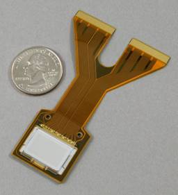
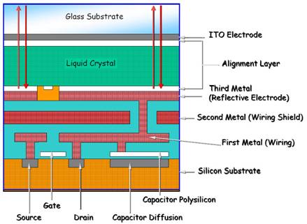
So how does it work? Liquid Crystal can rotate the polarization of light, and the amount of rotation can be controlled by an electric field. The electric field for each pixel is produced by a silicon chip behind the mirror. Actually, the mirror is the top layer of the silicon chip and the Liquid Crystal is placed directly on top of the mirror – so that’s why it’s called Liquid Crystal on Silicon. Most panels are about three quarters of an inch in size. Figure 2a shows a photograph of an LCoS panel. To produce an image a polarized light source is focused on the panel. The brightness of each pixel is controlled by varying the electric field at its location. This rotates the local light polarization and then a polarizing filter is used to block the portion that’s been rotated. The silicon chip that is generating the electric fields actually works very much like a computer memory chip and is organized into rows and columns of pixels. Each pixel is addressed as a memory location. A cross section diagram of an LCoS panel is shown in Figure 2b.


Just as with all of the other display technologies each manufacturer has their own proprietary implementation and all give their version a unique marketing name, which are listed in Tables 1 and 2. All of the manufacturers make a point of mentioning that they use a Vertically Aligned Neumatic Liquid Crystal with an inorganic alignment layer. The vertical alignment increases the contrast and also makes the screen naturally black when the drive signal is zero. The inorganic alignment layer eliminates the aging problems that arose with the earlier organic alignment layers, so all of these LCoS technologies now have very long lifetimes.


Table 2 lists the specifications supplied by each manufacturer for their higher technology 1080 LCoS panels. For completeness we have included information from Sony and SpatiaLight, which did not participate in the Shoot-Out. There are two entries for Sony: their first generation panels in the Qualia 004 and 006 products and their second generation panels in the XBR products announced in August 2005.


Table 2 : Specifications for 1920×1080 LCoS Panels


Brillian

eLCOS

JVC

Consumer

JVC

Professional

Sony

Qualia

Sony

XBR

SpatiaLight

LCoS

Technology

Gen II LCoS

eXTREME

digital

D-ILA

D-ILA

SXRD

SXRD

ImagEngine

Panel

Contrast Ratio

> 6000

> 6000

> 5000

> 5000

> 3000

5000

> 3500

Panel Size

0.70 inch

0.70 inch

0.70 inch

0.82 inch

0.78 inch

0.61 inch

0.74 inch

Pixel Pitch

8.1 microns

8.1 microns

8.1 microns

9.5 microns

9 microns

7 microns

8.5 microns

Inter-Pixel Gap

0.4 microns

0.45

microns

0.45

microns

0.45 microns

0.35 microns

0.35

microns

0.5 microns

Fill Factor

90 percent

89 percent

89 percent

91 percent

92 percent

90 percent

89 percent

Liquid Crystal

Thickness

NA

< 3 microns

3.5 microns

3 microns

< 2 microns

< 2 microns

NA

Lifetime

NA

> 100,000

hours

> 100,000

hours

> 100,000

hours

NA

NA

> 100,000

hours

Device Control

Analog

Voltage

Pulse Width

Modulation

Pulse Width

Modulation

Analog

Voltage

Analog

Voltage

Analog

Voltage

Analog

Voltage

Signal Level

12 bits

10.5 bits

10 bits

12 bits

NA

NA

10 bits

Rise Time

4 ms

2 ms

< 2.5 ms

3 ms

NA

2.5 ms

2.4 ms

Fall Time

4 ms

5 ms

NA

4 ms

NA

2.5 ms

3.3 ms

Response Time

8 ms

7 ms

NA

7 ms

5 ms

5 ms

6 ms


The Panel Contrast Ratio is probably the most critical value in the table because the Contrast Ratio at the screen of an HDTV is always less than the panel’s value. The Pixel Pitch is the center-to-center spacing for pixels in the panel and the Inter-Pixel Gap is the inactive space between them. The Fill Factor, sometimes called the Aperture Ratio, is the percentage of the pixel area that is active, which is close to 100 percent, so the gaps between the pixels on the screen are generally not noticeable. The Fill Factor is up to a few percentage points greater than for DLP microdisplays, but high temperature polysilicon LCD projector panels typically have much smaller values in the range of 50 to 70 percent, so their pixel structure is often noticeable. The Lifetime figure includes many factors, but can only be statistically estimated through extrapolation of laboratory testing. All of the supplied values are greater than 100,000 hours, which is more than 11 years running continuously 24 hours per day. Of greatest concern is the loss of brightness or contrast over time, which is called aging and can lead to what is commonly called image burn-in. All of the manufactures stated that aging and burn-in do not occur with their inorganic alignment layer. Signal Level refers to the number data bits used for controlling the LCoS device in the Panel Board. The greater the number of bits used the smoother the gray-scale and the less likely that false contouring will be visible.


The Response Time is an industry standard that specifies the total time that it takes a pixel to make a transition from black to white, the Rise Time or Ton, plus the time to make a transition from white to black, the Fall Time or Toff. Response Time is one measure of how quickly the image can be changed and provides some indication of the likelihood of visible motion smear in moving images. In general, the smaller the better, but there are many factors that are involved with motion smear. Unfortunately, some manufacturers are publishing a Response Time that is the average of the rise and fall times instead of their sum. This makes them appear to be twice as fast as they really are. So be very cautious with Response Time specifications – make sure you know which method the manufacturer is using. (As an example: Sony’s Qualia SXRD panels specify the total time, 5 ms, for the Response Time specification, but the latest XBR SXRD panels use the average, 2.5 ms, for the Response Time, so they appear to be twice as fast, when they’re not.) We have listed both the Rise and Fall Times in the Table to help clarify this issue.


The physical process that controls the brightness of each pixel is actually analog for LCoS and all other Liquid Crystal based technologies. This is an advantage because human vision is also an analog process as well. This eliminates the dithering artifacts that accompany fully digital display technologies like DLP and Plasma (See Part III, Part IV and Part D). However, it’s actually possible to design the panel’s silicon backplane to run with either an analog voltage or Pulse Width Modulation, PWM, which is a digital signal. The end result is still an analog response of the Liquid Crystal but it’s done in two entirely different ways and they each have their own advantages and disadvantages, which we’ll discuss later. (The digital method is similar to how the lowly light dimmer controls an analog tungsten lamp by using electrical pulses.) The Device Control entry in Tables 1 and 2 lists the method each unit uses. Digital backplanes generally have a higher yield and are therefore cheaper to manufacturer (but not all of the manufacturers agree with this statement), plus the associated drive electronics are also cheaper. However, it’s currently harder to get a smooth gray-scale with digital control (particularly at the dark-end of the gray-scale), so that’s why most units use analog backplanes.


Figure 2a


Figure 2b


Figure 2c

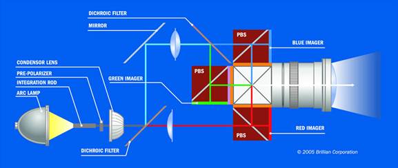
Caption: Figure 2. (a) LCoS D-ILA panel photograph. Courtesy JVC. (b) LCoS D-ILA panel cross section diagram. Courtesy JVC Professional Products. (c) Projection Light Engine. Courtesy Brillian Corporation.


Optics and Electronics

There are a number of other critical components in an LCoS HDTV besides the panels. The Projection Light Engine, which contains all of the optics from the lamp to the projection lens, first prepares the light beams that illuminate the tiny LCoS panels, and then magnifies the images by a linear scale factor of about 80 to one, which is 6,400 to one in area (for a typical 60 inch diagonal screen). The technology involved is no less amazing than the LCoS panels themselves and is just as important to the image and picture quality you see on the screen. It’s generally the single most expensive component in any projection HDTV. Figure 2c shows a diagram of a Projection Light Engine. Note that all of these HDTVs use 3 LCoS panels, one for each of the red, green and blue primary color channels. Filters first split the light into the 3 primary color components for the LCoS panels, and then a set of prisms is used to recombine the primary colors back into a single beam just ahead of the projection lens. The screen itself is another major component in the optical system. It also has a critical impact on image and picture quality and the good ones are quite expensive. There are two other important optical components: the very black interior space between the projection lens and screen that absorbs spurious light and a front-surface flat mirror at the back of the cabinet that redirects the light path from the projection lens forward to the screen.


There are two main electronic component assemblies that we will also be discussing frequently: the Panel Board, which is responsible for the low-level direct control of the LCoS panels, and the Front-End Board, which has all of the input connectors for the HDTV. It converts all of the various input signals (Composite Video, S-Video, Component Video, RGB, DVI and HDMI) into the digital format required by the Panel Board. It also manages the On Screen Menus that implement the user and service adjustments and controls. The Panel Board generally has only factory accessible controls, including the low-level device gamma tables needed to control the LCoS panels.


What’s Coming Next

In Part B we'll start with a discussion of How We Tested and then examine the photometry and colorimetry of the units in detail, which provides a quantitative assessment of their color and gray-scale accuracy. In Part C we'll continue with a revealing Test Pattern analysis, followed by a description of the extensive Jury Panel testing and then provide individual Assessments for each of the units, including Jury evaluations and comments. Part D will have an overall Assessment of LCoS technology, followed by detailed technical performance comparisons between all of the major display technologies: CRT, LCD, Plasma, DLP, and LCoS, and we’ll finish with a discussion of the most exciting new developments in display technology that will be the subject of future articles in this series.


Article Links

Series Overview

Part A: Introduction to LCoS Technology

Part B: LCoS Color and Gray-Scale Accuracy

Part C: Test Pattern and Jury Panel Evaluations

Part D: Comparison with CRT, LCD, Plasma and DLP


Sidebar: LCoS HDTV Manufacturers

Sidebar: Shoot-Out Hardware and Software


Acknowledgements

Over 75 people were involved with the Shoot-Out: about half were participating manufacturers and the other half were Panelists (see Part C) that came to evaluate the HDTVs.


Special Thanks: A number of people made important contributions that warrant a special mention: special thanks to Dr. Edward F. Kelley of the NIST (National Institute of Standards and Technology) for many interesting discussions and for generously sharing his expertise. Special thanks to Dave Migliori for his excellent photography of the Shoot-Out with its difficult lighting layout and viewing angles. Special thanks to Julia Soneira and Lauren Soneira for helping to produce the Shoot-Out, which turned out to be a much larger operation than I had anticipated. And finally, very special thanks to Hope Frank (Brillian), David McDonald (eLCOS), Terry Shea (JVC Consumer) and Rod Sterling (JVC Professional) for the tremendous amount of work that they put in coordinating their company’s efforts, which was crucial for making the Shoot-Out a success.


HDTV Manufacturers: Brillian Corporation: Hope Frank (Vice-President), Chad Goudie, Douglas Gorny, Gil Hazenschprung, Dr. Robert Melcher (Chief Technology Officer), Dr. Matthias Pfeiffer, Jack Waterman. eLCOS Microdisplay Technology: Dr. David J. Cowl, Roland Lue, David McDonald. JDS Uniphase: Michael Newell, Dr. Andrew Taylor. JVC (Consumer Division): Dan McCarron, Terry Shea, Fumi Usuki. JVC Professional Products: Dr. William Bleha, Ken Bylsma, Jack Faiman (Vice-President), Gary Klasmeier, Rod Sterling. SpatiaLight Technologies: Ted Banzhaf (President), Dr. David Hakala (Chief Operating Officer).


About the Author

Dr. Raymond Soneira is President of DisplayMate Technologies Corporation of Amherst, New Hampshire, which produces video calibration, evaluation, and diagnostic products for consumers, technicians, and manufacturers. See www.displaymate.com. He is a research scientist with a career that spans physics, computer science, and television system design. Dr. Soneira obtained his Ph.D. in Theoretical Physics from Princeton University, spent 5 years as a Long-Term Member of the world famous Institute for Advanced Study in Princeton, another 5 years as a Principal Investigator in the Computer Systems Research Laboratory at AT&T Bell Laboratories, and has also designed, tested, and installed color television broadcast equipment for the CBS Television Network Engineering and Development Department. He has authored over 35 research articles in scientific journals in physics and computer science, including Scientific American. If you have any comments or questions about the article, you can contact him at dtso@displaymate.com.


Copyright © 1990-2006 by DisplayMate Technologies Corporation. All Rights Reserved.
This article, or any part thereof, may not be copied, reproduced, mirrored, distributed or incorporated
into any other work without the prior written permission of DisplayMate Technologies Corporation


--------------------
Copyright © 1990-2009 by DisplayMate® Technologies Corporation. All Rights Reserved.
Click here for Copyright, Trademark, Warranty Information and Legal Terms of Use

Screen Resolution: This site best viewed at a resolution format of 1280x1024 pixels or greater.
Printing: If your browser is improperly printing some pages with text cutoff on the right edge then print in
Landscape mode or reduce the font size (View Menu - Text Size) and margins (File Menu - Page Setup).